While you can use a Global Positioning System (GPS) unit to navigate from point A to point B without a map, for purposes of hiking and backpacking navigation, GPS should be considered as a supplemental tool to use WITH your map and compass. In a search and rescue context, with your GPS unit you can tell a search team or helicopter pilot exactly where you are.
GPS units range from around $150 to over $600 for hand held units suitable for personal navigation. You should take the time to practice with a GPS receiver before you try to understand the technical details of the GPS system. They are surprisingly simple to use, given all the technology involved. You can learn most of what you need to know within and hour or two of opening the box. They usually come with a tutorial, use it! It only takes about 30 minutes to follow this tutorial and you will learn a great deal in a short period of time.
What is GPS?
The following information is from Wikipedia as of May 3, 2012. A lot more information is available at http://en.wikipedia.org/wiki/Global_Positioning_System
The Global Positioning System (GPS) is a space-based satellite navigation system that provides location and time information in all weather, anywhere on or near the Earth, where there is an unobstructed line of sight to four or more GPS satellites. It is maintained by the United States government and is freely accessible to anyone with a GPS receiver.
The GPS program provides critical capabilities to military, civil and commercial users around the world. In addition, GPS is the backbone for modernizing the global air traffic system.
The GPS project was developed in 1973 to overcome the limitations of previous navigation systems, integrating ideas from several predecessors, including a number of classified engineering design studies from the 1960s. GPS was created and realized by the U.S. Department of Defense (DoD) and was originally run with 24 satellites. It became fully operational in 1994.
Advances in technology and new demands on the existing system have now led to efforts to modernize the GPS system and implement the next generation of GPS III satellites and Next Generation Operational Control System (OCX). Announcements from the Vice President and the White House in 1998 initiated these changes. In 2000, U.S. Congress authorized the modernization effort, referred to as GPS III.
In addition to GPS, other systems are in use or under development. The Russian GLObal NAvigation Satellite System (GLONASS) was in use by only the Russian military, until it was made fully available to civilians in 2007. There are also the planned European Union Galileo positioning system, Chinese Compass navigation system, and Indian Regional Navigational Satellite System.
How It Works
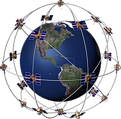
Basic concept of GPSA GPS receiver calculates its position by precisely timing the signals sent by GPS satellites high above the Earth. Each satellite continually transmits messages that include
A visual example of the GPS constellation in motion with the Earth rotating. Notice how the number of satellites in view from a given point on the Earth's surface, in this example at 45ºN, changes with time.
The receiver uses the messages it receives to determine the transit time of each message and computes the distance to each satellite. These distances along with the satellites' locations are used with the possible aid of trilateration, depending on which algorithm is used, to compute the position of the receiver. This position is then displayed, perhaps with a moving map display or latitude and longitude; elevation information may be included. Many GPS units show derived information such as direction and speed, calculated from position changes.
Three satellites might seem enough to solve for position since space has three dimensions and a position near the Earth's surface can be assumed. However, even a very small clock error multiplied by the very large speed of light - the speed at which satellite signals propagate - results in a large positional error.
Therefore receivers use four or more satellites to solve for both the receiver's location and time. The very accurately computed time is effectively hidden by most GPS applications, which use only the location.
A few specialized GPS applications do however use the time; these include time transfer, traffic signal timing, and synchronization of cell phone base stations.
Although four satellites are required for normal operation, fewer apply in special cases. If one variable is already known, a receiver can determine its position using only three satellites.
For example, a ship or aircraft may have known elevation. Some GPS receivers may use additional clues or assumptions (such as reusing the last known altitude, dead reckoning, inertial navigation, or including information from the vehicle computer) to give a less accurate (degraded) position when fewer than four satellites are visible.
User segment

The user segment is composed of hundreds of thousands of U.S. and allied military users of the secure GPS Precise Positioning Service, and tens of millions of civil, commercial and scientific users of the Standard Positioning Service.
In general, GPS receivers are composed of an antenna, tuned to the frequencies transmitted by the satellites, receiver-processors, and a highly stable clock (often a crystal oscillator). They may also include a display for providing location and speed information to the user.
A receiver is often described by its number of channels: this signifies how many satellites it can monitor simultaneously. Originally limited to four or five, this has progressively increased over the years so that, as of 2007, receivers typically have between 12 and 20 channels.
GPS receivers may include an input for differential corrections, using the RTCM SC-104 format. This is typically in the form of an RS-232 port at 4,800 bit/s speed. Data is actually sent at a much lower rate, which limits the accuracy of the signal sent using RTCM.
Receivers with internal DGPS receivers can outperform those using external RTCM data. As of 2006, even low-cost units commonly include Wide Area Augmentation System (WAAS) receivers.
Many GPS receivers can relay position data to a PC or other device using the NMEA 0183 protocol. Although this protocol is officially defined by the National Marine Electronics Association (NMEA), references to this protocol have been compiled from public records, allowing open source tools like gpsd to read the protocol without violating intellectual property laws. Other proprietary protocols exist as well, such as the SiRF and MTK protocols. Receivers can interface with other devices using methods including a serial connection, USB, or Bluetooth.
How Accurate is GPS?
Today's GPS receivers are extremely accurate.
A GPS receiver used in a stand-alone (handheld) mode can provide accuracies within +/-15 meters of a true position. Variations in accuracy can be attributed to one or more of the following factors:
Garmin, a major supplier of GPS receivers, states that thanks to their parallel multi-channel design, Garmin's 12 parallel channel receivers are quick to lock onto satellites when first turned on and they maintain strong locks, even in dense foliage or urban settings with tall buildings. Certain atmospheric factors and other sources of error can affect the accuracy of GPS receivers. Garmin® GPS receivers are accurate to within 15 meters on average.
Newer Garmin GPS receivers with WAAS (Wide Area Augmentation System) capability can improve accuracy to less than three meters on average. No additional equipment or fees are required to take advantage of WAAS.
Users can also get better accuracy with Differential GPS (DGPS), which corrects GPS signals to within an average of three to five meters. The U.S. Coast Guard operates the most common DGPS correction service. This system consists of a network of towers that receive GPS signals and transmit a corrected signal by beacon transmitters. In order to get the corrected signal, users must have a differential beacon receiver and beacon antenna in addition to their GPS.
How Do I Use GPS To Find My Way?
The GPS receiver helps determine locations on the Earth's surface by collecting signals from three or more satellites through a process called trilateration. Identifying a location on the Earth is more useful if you also know about the surrounding topographic conditions. Using a topographic map with the GPS receiver provides important information about features of the surrounding terrain and can help you plot an effective route from one location to another.
Using Topographic Maps With the GPS
When using a topographic map with a GPS receiver, you need to ensure that the receiver has been programmed correctly to account for variables such as:
Refer to the instructions that accompany the specific receiver being used to ensure that these variables are entered correctly.
Map Projections
The most convenient way to identify points on the curved surface of the Earth is with a system of reference lines called parallels of latitude and meridians of longitude. On some maps, the meridians and parallels appear as straight lines. On most modern maps, however, the meridians and parallels appear as curved lines.
These differences are due to the mathematical treatment required to portray a curved surface on a flat surface so that important properties of the map (such as distance and areal accuracy) are shown with minimum distortion. The system used to portray a part of the round Earth on a flat surface is called a map projection.
Grids
To simplify the use of maps and to avoid the inconvenience of pinpointing locations on curved reference lines, cartographers superimpose on the map a rectangular grid consisting of two sets of straight, parallel lines, uniformly spaced, each set perpendicular to the other.
This grid is designed so that any point on the map can be designated by its latitude and longitude or by its grid coordinates, and a reference in one system can be converted into a reference in another system. Such grids are usually identified by the name of the particular projection for which they are designed.
Figure 1. The Universal Transverse Mercator grid that covers the conterminous 48 United States comprises 10 zones—from Zone 10 on the west coast through Zone 19 in New England.
The Universal Transverse Mercator Grid
The National Imagery and Mapping Agency (NIMA) (formerly the Defense Mapping Agency) adopted a special grid for military use throughout the world called the Universal Transverse Mercator (UTM) grid.
In this grid, the world is divided into 60 north-south zones, each covering a strip 6° wide in longitude. These zones are numbered consecutively beginning with Zone 1, between 180° and 174° west longitude, and progressing eastward to Zone 60, between 174° and 180° east longitude. Thus, the conterminous 48 States are covered by 10 zones, from Zone 10 on the west coast through Zone 19 in New England (figure 1).
In each zone, coordinates are measured north and east in meters. (One meter equals 39.37 inches, or slightly more than 1 yard.) The northing values are measured continuously from zero at the Equator, in a northerly direction. To avoid negative numbers for locations south of the Equator, NIMA's cartographers assigned the Equator an arbitrary false northing value of 10,000,000 meters. A central meridian through the middle of each 6° zone is assigned an easting value of 500,000 meters. Grid values to the west of this central meridian are less than 500,000; to the east, more than 500,000.
Virtually all NIMA-produced topographic maps and many aeronautical charts show the UTM grid lines.
Determining a UTM Grid Value for a Map Point
Figure 2. The grid value of line A-A is 357,000 meters east. The grid value of line B-B is 4,276,000 meters north. Point P is 800 meters east and 750 meters north of the grid lines; therefore, the grid coordinates of point P are north 4,276,750 and east 357,800.
The UTM grid is shown on all quadrangle maps prepared by the U.S. Geological Survey (USGS). On 7.5-minute quadrangle maps (1:24,000 and 1:25,000 scale) and 15-minute quadrangle maps (1:50,000, 1:62,500, and standard-edition 1:63,360 scales), the UTM grid lines are indicated at intervals of 1,000 meters, either by blue ticks in the margins of the map or with full grid lines. The 1,000-meter value of the ticks is shown for every tick or grid line. In addition, the actual meter value is shown for ticks nearest the southeast and northwest corners of the map. Provisional maps at 1:63,360 scale show full UTM grids at 5,000-meter intervals.
To use the UTM grid, you can place a transparent grid overlay on the map to subdivide the grid, or you can draw lines on the map connecting corresponding ticks on opposite edges. The distances can be measured in meters at the map scale between any map point and the nearest grid lines to the south and west. The northing of the point is the value of the nearest grid line south of it plus its distance north of that line; its easting is the value of the nearest grid line west of it plus its distance east of that line (see fig. 2).
On maps at 1:100,000 and 1:250,000 scale, a full UTM grid is shown at intervals of 10,000 meters and is numbered and used in the same way.
This page, Example of How To Use UTM, provides a good set of instructions on how to use UTM with your map.
The Universal Transverse Mercator (UTM) Grid System by Blake Miller
Map Tools Tutorials including Map, Compass and GPS Tutorials from map tools.com
The United States Geological Survey (USGS) provides a gigantic amount of mapping, geography, and related materials on the internet for active viewing and in various electronic and printed forms. Teaching materials for grade school and up are available at http://education.usgs.gov/lessons/mapresources.html. Much of the material is available for viewing and immediate use on-line.
For additional information, visit the USGS home page at www.usgs.gov.

Topographic Map Tools
Both the UTM and the Latitude/Longitude coordinate systems allow GPS positions to be plotted on a map and map positions to be entered into the GPS. A number of coordinate reading tools are available for purchase on-line.
So How Do You Use This Information
To travel from point A to point B on your map, determine the coordinates for each point on your map and enter them in your GPS and let it guide you there. You can also enter "way-points" along the route you wish to follow. It is important to remember that for your safety, if batteries die, that you need a compass in addition to the GPS unit and map.
To find out where your are on your map, read the coordinates from your GPS and mark them on your map. This location information can also be provided by cell phone to a Search and Rescue Base so they can radio your location to a ground search team or to a helicopter so that they can find you in a search and rescue situation.
Additional Information Sources
Keep in mind that GPS has a multitude of uses well beyond navigating in the wilderness. As a result, many of the information sources contain material that goes beyond the hand held navigator's needs ... but these sources may also have useful information for you.
Gaia GPS is a highly rated app for your iPhone or Android phone to use for back county and other travel that provides on-line and off-line access to topographic maps and trip planning capabilities. Recommended by the Columbia River Orienteering Club. This video tutorial will show you the capabilities of the June 2017 version.